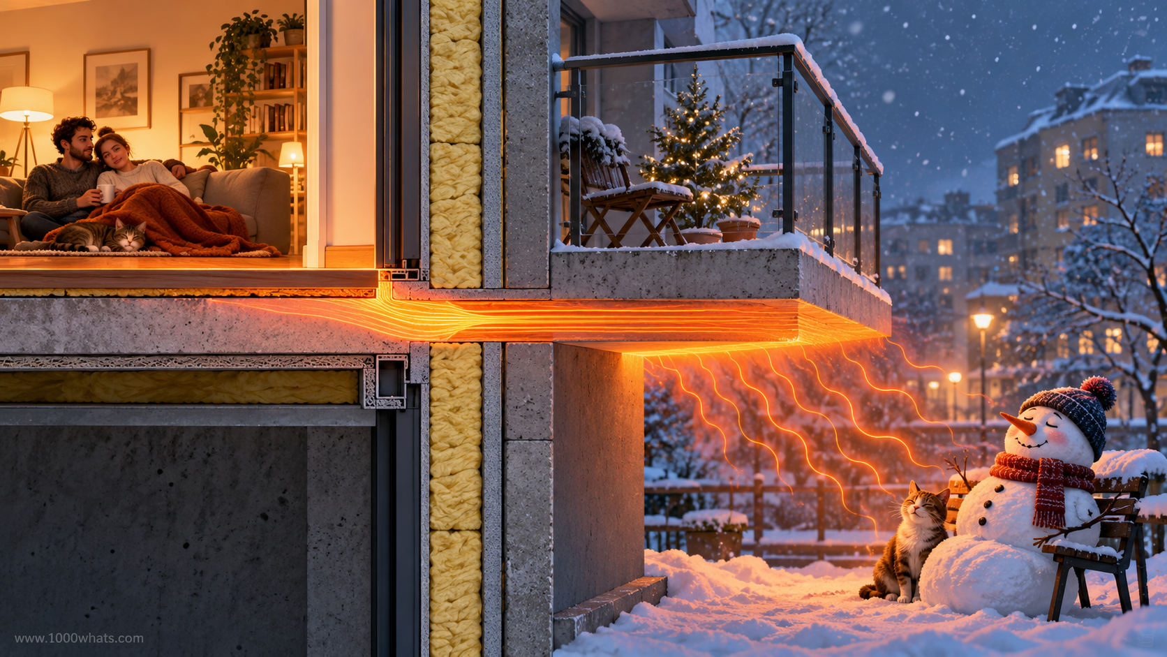
Your apartment is warm. The windows are shut. The insulation is new. The heating bill is still behaving like a ransom note.
Meanwhile, your concrete balcony is outside in January, quietly warming the neighborhood.
Nobody asked it to. Nobody is standing underneath with a mug and a thank-you card. But the balcony has found a way to carry heat out of your home, and it intends to keep doing so until spring.
This is not a story about a hole in the wall. The wall can be perfectly airtight. The balcony can be beautifully built. The insulation installer may have taken photographs, collected payment, and gone home feeling like a champion.
The problem is that the building’s structure has created a shortcut for heat.
Welcome to 1000whats, where today we discover that a building can wear an excellent winter coat while leaving one arm sticking out of the sleeve.
That shortcut is called a thermal bridge. And once you know what to look for, you will start seeing its architectural accomplices everywhere.
Meet the balcony with an expensive hobby
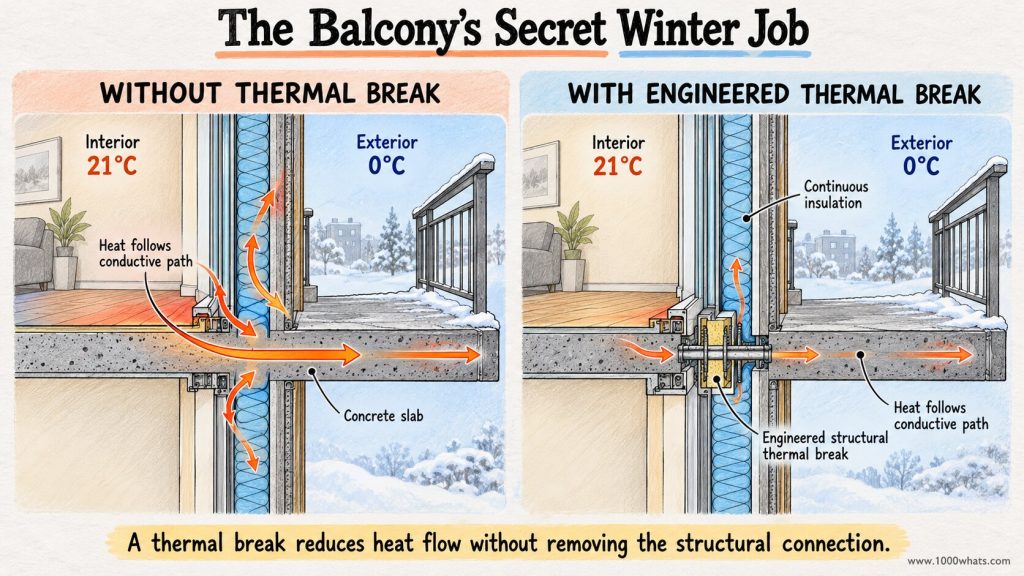
Imagine a concrete floor slab inside an apartment. It extends through the exterior wall and continues outside to form a balcony.
Inside, the slab is warm. Outside, it is cold. Between them is a continuous piece of concrete, a material chosen because it can support a considerable amount of weight without developing a personal crisis.
Unfortunately, concrete is also much better at conducting heat than most insulation materials.
So the building has two routes for heat to escape. Route one goes through the insulated wall, which is designed to make heat travel slowly. Route two goes along the continuous concrete slab, which is considerably less interested in your heating budget.
The insulation says, “You’ll have to get through me.”
The balcony replies, “I know a guy.”
That second route is a thermal bridge. Heat is not crossing the balcony because it is attracted to balconies. It is moving from a warmer region toward a colder one, and the construction provides a path with relatively low thermal resistance.
The U.S. Department of Energy’s Building America guidance identifies balconies, slab edges, steel framing, and cladding supports as common places where structural connections interrupt an insulated building envelope.
The engineering challenge is not to abolish the balcony. Residents would have questions. It is to preserve the structural connection while reducing the unwanted thermal connection.
What is a thermal bridge, exactly?
A thermal bridge is a localized region of a building envelope where heat flows more readily than through the surrounding construction, often because a more conductive material, an interrupted insulation layer, or the geometry of a junction creates a lower-resistance path.
It can be a strip, a line, or a small point. It can be hidden behind plaster. And it can matter even when no air passes through it.
In winter, the usual concern is heat moving from indoors to outdoors. In summer, the same conductive pathway can help unwanted heat enter a cooled building. Thermal bridges do not have seasonal loyalty. They merely follow temperature differences.
Here are some familiar suspects:
| Location | What creates the shortcut? | Why it matters |
|---|---|---|
| Concrete balcony | Slab continues from warm interior to cold exterior | Extra heat loss and a colder interior floor edge |
| Steel stud wall | Metal framing crosses the insulated wall depth | Repeating conductive paths across a large area |
| Window perimeter | Frame and wall insulation meet poorly | Cold reveals, discomfort, possible moisture risk |
| Roof-to-wall junction | Insulation layers fail to connect continuously | Heat escapes along a long roofline |
| Floor slab edge | Concrete reaches or interrupts the facade insulation | A cold horizontal stripe at each story |
| Cladding bracket | Metal fastener or support penetrates insulation | Many small paths can add up |
Notice that some of these are ordinary structural necessities. The wall needs studs. The balcony needs support. The window cannot simply hover in the air while everyone admires its thermal performance.
The aim is better detailing, not a building made entirely of foam and optimism.
Heat does not look for holes. It looks for an easier route.
We should separate three ideas that often get thrown into one unhappy bucket.
Conduction is heat transfer through materials. Thermal bridging is primarily a conduction problem, though real junctions involve multidimensional heat flow and surface heat transfer too.
Air leakage is air physically moving through cracks or gaps. A draft around a window is an air-sealing problem, even if the same window detail also has a thermal bridge.
Moisture leakage is liquid water getting somewhere it should not, for example through failed flashing. That is another problem again.
A thermal bridge can exist in an airtight, dry wall. A draft can exist in a well-insulated wall. A rain leak can soak a perfectly respectable piece of insulation and make the whole situation much worse.
The symptoms overlap, but the fixes do not always overlap. Caulk may stop a draft. It will not magically turn a continuous steel beam into an insulator.
This distinction is central to building diagnostics. The Department of Energy’s home assessment guidance describes infrared scans and blower-door tests as complementary methods for finding problems in the building envelope.
If a contractor proposes solving every cold wall with a tube of sealant, you may be dealing with a very enthusiastic tube-of-sealant salesperson.
The two numbers that make walls confess
Before we calculate the balcony’s side business, meet two useful quantities.
Thermal conductivity, usually written as lambda (λ), describes how readily a material conducts heat. Its SI unit is W/(m·K). Lower conductivity generally means a better insulating material, all else equal.
Thermal transmittance, or U-value, describes the heat flow through an entire building element per square meter for each degree of temperature difference. Its unit is W/(m²·K). Lower U-value means less heat loss through that element under the same conditions.
A U-value accounts for the assembly, not just the fluffy material inside it. Layers, surfaces, framing, and installation details all matter.
The familiar steady-state calculation is:
Heat-loss rate = U × area × temperature difference
Or:
P = U × A × ΔT
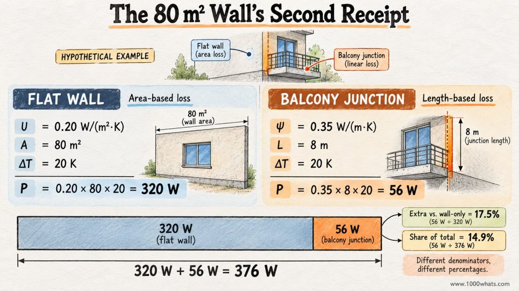
Suppose an 80 m² exterior wall has an effective U-value of 0.20 W/(m²·K). Inside is 20°C; outside is 0°C. The temperature difference is 20 K, which is also a difference of 20°C.
P = 0.20 × 80 × 20 = 320 W
The wall is losing heat at a rate of 320 watts under those assumed steady conditions.
That is power, not energy. Hold those conditions for one hour and the loss would be 0.32 kWh of heat. Hold them for ten hours and it would be 3.2 kWh.
If watts and watt-hours are still having an argument in your head, my guide to power versus energy can referee.
So far, the calculation looks tidy. Almost suspiciously tidy.
Then the balcony walks into the spreadsheet.
The 80-square-meter wall gets a second bill
A balcony junction is not conveniently measured in square meters. Its thermal effect extends along a line, such as the eight-meter length where a slab meets the exterior wall.
Engineers use a quantity called linear thermal transmittance, written with the Greek letter psi (ψ). Its unit is W/(m·K).
For a defined junction and reference geometry, ψ expresses the heat-flow contribution beyond the heat already counted in the adjacent flat building elements’ U-values. The reference dimensions and modeling conventions matter. A psi-value is not a universal property of concrete.
For a simple illustrative calculation, assume:
- Wall area: 80 m².
- Wall U-value: 0.20 W/(m²·K).
- Balcony junction length: 8 m.
- Balcony junction ψ-value: 0.35 W/(m·K).
- Indoor-outdoor temperature difference: 20 K.
The ψ-value is an invented project-specific assumption for teaching, not a measured result or a typical value guaranteed for every balcony.
The extra heat-loss rate associated with that junction is:
P_bridge = ψ × length × ΔT
P_bridge = 0.35 × 8 × 20 = 56 W
So the wall’s flat-area calculation gives 320 W, while the balcony junction adds 56 W under this consistent illustrative accounting convention.
Total = 320 + 56 = 376 W
That extra 56 W is 17.5% of the original wall-only heat-loss rate. As a share of the new 376 W total, it is about 14.9%. Both percentages are correct. They simply answer different questions.
| Heat-loss component | Formula | Result at ΔT = 20 K |
|---|---|---|
| Flat wall | 0.20 × 80 × 20 | 320 W |
| Balcony junction | 0.35 × 8 × 20 | 56 W |
| Combined | 320 + 56 | 376 W |
| Extra relative to wall-only result | 56 / 320 | 17.5% |
One balcony has not defeated the entire heating system. But it has added a measurable burden that the flat-wall calculation missed.
And in a building with many floors, balconies, windows, slab edges, and other junctions, the extras can accumulate like restaurant service charges that nobody mentioned when you ordered.
How a few watts turn into an annual energy bill
A watt measures the rate of heat loss at a particular temperature difference. To estimate annual heating energy, we need to account for how cold it is and for how long.
A common simplified tool is heating degree-days. One degree-day represents a one-kelvin temperature difference sustained for one day. The choice of indoor or balance-point reference temperature is important, and standard published heating degree-days may use a different base from our example.
Assume, purely for this worked example, 2,500 K·days of accumulated indoor-outdoor temperature difference over the heating season, consistent with the reference used in our simple heat-loss model.
Then:
Annual bridge heat loss ≈ ψ × length × degree-days × 24 / 1,000
= 0.35 × 8 × 2,500 × 24 / 1,000
= 168 kWh of heat per heating season
The flat wall contributes:
0.20 × 80 × 2,500 × 24 / 1,000 = 960 kWh of heat
Combined: 1,128 kWh of modeled transmission heat loss through this wall-plus-junction accounting example.
These are not a prediction of a household’s total heating bill. Real heating demand depends on solar and internal gains, ventilation, thermostat schedules, weather, heating-system performance, and many other envelope elements. This calculation deliberately isolates one part of the building.
Now give the balcony a proper thermal break and suppose its modeled ψ-value falls from 0.35 to 0.06 W/(m·K), with the same reference geometry.
The new junction loss becomes:
0.06 × 8 × 2,500 × 24 / 1,000 = 28.8 kWh of heat per season
The modeled reduction is 139.2 kWh of heat per season.
If that heat would otherwise be supplied by a heat pump with an assumed seasonal COP of 3, the corresponding electricity saving would be approximately 46.4 kWh. At a hypothetical €0.25/kWh, that is €11.60 a year for this one junction.
| Balcony junction | Before thermal break | After thermal break |
|---|---|---|
| Assumed ψ-value | 0.35 W/(m·K) | 0.06 W/(m·K) |
| Junction length | 8 m | 8 m |
| Annual transmission heat loss | 168.0 kWh | 28.8 kWh |
| Reduction | Not applicable | 139.2 kWh of heat |
| Electricity equivalent at COP 3 | 56.0 kWh | 9.6 kWh |
If that saving seems modest, good. We have not secretly turned one balcony into a small power plant to make the economics look exciting. The benefit of fixing a thermal bridge can also include warmer interior surfaces, better comfort, and reduced moisture risk. In some projects, those benefits matter more than the simple annual energy saving.
And the cost of a structural thermal break belongs in the design and construction budget. Retrofitting a finished balcony is a very different, often much harder proposition.
The other bridge is hiding in your perfectly ordinary wall
Not every thermal bridge arrives as an eight-meter concrete slab. Some arrive in hundreds of smaller installments.
Take a wood-framed wall. Between the studs is insulation. Through the studs is wood. Wood is useful for holding the wall together, but it is generally a poorer insulator than the material packed between the studs.
The DOE’s Building Science Education guidance explains why continuous exterior insulation helps: conventional framing can occupy a substantial fraction of the wall area, creating repeated paths of higher heat flow.
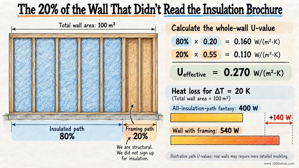
Here is a deliberately simplified parallel-path model. Imagine a 100 m² wall with:
- 80% of its area following an insulated path with U = 0.20 W/(m²·K).
- 20% following a framing path with U = 0.55 W/(m²·K).
Those are hypothetical whole-path U-values, including the relevant layers and surface resistances. We are not comparing the conductivity of bare wood with the U-value of a finished wall.
For this simplified model:
U_effective = 0.80 × 0.20 + 0.20 × 0.55
U_effective = 0.27 W/(m²·K)
That is 35% higher than the insulation-path U-value of 0.20. Higher U means more heat escapes.
At a 20 K temperature difference across 100 m²:
- Imaginary wall made entirely of the better-insulated path: 400 W.
- Wall with the assumed 20% framing fraction: 540 W.
- Difference: 140 W.
For 2,500 K·days on the same simplified basis, the difference becomes 420 kWh of heat.
| Path | Area share | Assumed path U-value | Contribution to effective U |
|---|---|---|---|
| Insulated cavities | 80% | 0.20 W/(m²·K) | 0.160 W/(m²·K) |
| Framing | 20% | 0.55 W/(m²·K) | 0.110 W/(m²·K) |
| Combined wall | 100% | Not applicable | 0.270 W/(m²·K) |
Real wall calculations can require more sophisticated methods because heat spreads sideways, and the materials are not always neat parallel strips. The point is the accounting principle: the insulation label is not automatically the performance of the entire wall.
It is the architectural equivalent of buying a waterproof jacket and then discovering that 20% of it is decorative mesh.
Wait. Are studs and balconies counted in the same way?
Not necessarily. This is where otherwise excellent explanations accidentally double-count heat loss.
Repeating bridges, such as regularly spaced framing studs, are normally incorporated into the effective U-value of the wall assembly.
Linear junction bridges, such as a floor-to-wall connection or balcony edge, are often accounted for separately using a ψ-value, depending on the chosen calculation convention.
Point bridges, such as certain discrete structural anchors, may be represented by a chi-value (χ) in W/K.
A simplified building transmission heat-loss coefficient can therefore be written as:
H_T = Σ(U × A) + Σ(ψ × length) + Σχ
The result is in W/K. Multiply it by the indoor-outdoor temperature difference in kelvins to obtain a steady heat-loss rate in watts.
The Passive House Institute’s technical explanation uses this framework and explicitly warns that repeating bridges already included in U-values must not be counted again as separate junction losses.
One more surprise: depending on the reference dimensions and geometry, a calculated ψ-value can even be negative. That does not mean a corner has become a heat pump. It means the two-dimensional junction calculation gives less heat loss than the particular one-dimensional reference-area calculation against which it is compared.
Reference dimensions matter. Double counting matters. The balcony does not get to invoice you twice because the spreadsheet is having a difficult day.
Why the coldest corner can become the dampest corner
Thermal bridges are not merely a question of annual kilowatt-hours. They also change interior surface temperatures.
Suppose the air inside a room is 21°C, and the relative humidity is 60%. Under those conditions, the dew point is approximately 12.9°C.
If a surface falls below that temperature, water vapor can condense on it. A cold surface can also develop high local relative humidity before liquid water appears.
Here is the counterintuitive part. The room air can be at 60% relative humidity while the air immediately next to a colder wall surface is much closer to saturation. The amount of water vapor need not increase. The saturation vapor pressure falls as the temperature falls.
For this example, assuming the same water-vapor partial pressure at the surface:
| Temperature | Approximate local relative humidity | What it suggests |
|---|---|---|
| Room air: 21°C | 60% | Ordinary indoor condition for this example |
| Surface: 16°C | 82% | Prolonged high surface humidity can support mold risk |
| Surface: 14°C | 93% | Very humid surface microclimate |
| Surface: 13°C | About 100% | Near the dew point; condensation may begin |
These values come from a standard saturation-vapor-pressure relationship, rounded for readability. They are not measured surface temperatures for any particular wall. A ψ-value by itself does not tell you the minimum surface temperature; junction geometry, materials, boundary conditions, and multidimensional heat-flow modeling are needed.
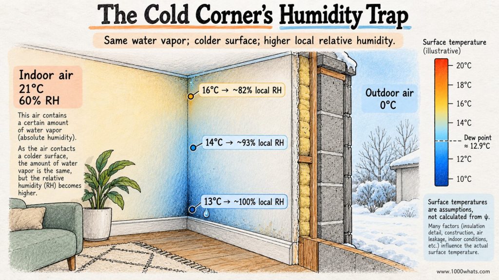
The Scottish Government’s building guidance on condensation identifies thermal bridges as possible cold-surface locations where condensation and mold can develop, with risk depending on humidity, ventilation, heating, and construction details.
That explains a familiar mystery: a room can feel warm, and the middle of its wall can be dry, while the corner behind a wardrobe becomes a thriving biological conference.
The mold did not arrive because the corner had a bad attitude. It found a cool, humid microclimate and a surface it liked.
Persistent dampness or mold deserves proper diagnosis and remediation. Covering it with paint and declaring victory is not a moisture-management strategy.
The thermal camera sees a clue, not a confession
An infrared camera can reveal patterns of surface temperature. In winter, a poorly insulated slab edge may appear as a cold band when viewed from inside, or a relatively warm band when viewed from outside.
That is useful. It is not the same as directly measuring heat flow through the wall.
Infrared images are affected by emissivity, reflected radiation, sunshine, wind, weather history, interior heating, and the temperature difference across the envelope. Moisture and air leakage can also create thermal patterns. Shiny glass is particularly fond of showing the camera things that are not the temperature of the glass itself.
The DOE’s home energy assessment guide describes thermography as a way to identify temperature differences, often used alongside a blower-door test. It is a diagnostic aid, not a magic X-ray of a building’s energy bill.
A good survey asks what caused the pattern, checks the building detail, and uses appropriate testing or modeling before prescribing a repair.
A blue stripe on a thermal image does not automatically mean “buy more insulation.” It may mean a slab edge, a gap, moving air, damp material, or an optical measurement problem.
The camera supplies the plot twist. Building physics still has to write the ending.
Why adding more insulation can make the remaining bridges look worse
Suppose you improve the flat wall’s U-value from 0.20 to 0.15 W/(m²·K), but leave the balcony junction unchanged at ψ = 0.35 W/(m·K).
At the same 80 m², 8 m, and 20 K:
- Improved flat wall: 0.15 × 80 × 20 = 240 W.
- Unchanged balcony junction: 56 W.
- Combined: 296 W.
You have reduced total heat loss from 376 W to 296 W. That is genuinely good.
But the balcony now accounts for 56 / 296 ≈ 18.9% of this combined loss, up from 14.9%.
The bridge did not become worse. The rest of the wall became better.
It is the same reason the one person who refuses to split the restaurant bill becomes much more noticeable after everyone else pays promptly.
This is why high-performance buildings pay so much attention to junctions. Once the broad wall and roof areas are excellent, the remaining weak points become proportionally more important.
The Passive House Institute describes thermal-bridge-free design as a central part of minimizing transmission losses, while also recognizing that the details must be calculated consistently.
The fixes are architectural, not supernatural
The most effective approach is usually to prevent a thermal bridge during design rather than attempt to repair it after residents have moved in and bought patio furniture.
For a balcony, that can mean a structurally engineered thermal-break connector, an independently supported balcony, or another detail that maintains load transfer while interrupting the conductive path.
For framed walls, continuous exterior insulation can cover the studs rather than leaving them as repeated paths through the insulation layer.
For windows, the frame position, insulation returns, and perimeter details matter. For roofs and foundations, the insulation layers need to meet without an accidental gap. For metal cladding, brackets and fasteners should be chosen and detailed with their thermal effect in mind.
The DOE Building America multifamily guide describes structural and insulation strategies for balconies, slab edges, steel framing, and cladding attachments. The DOE continuous-insulation guidance explains the same principle for conventional residential framing.
None of these choices can be made by looking at a ψ-value alone. A real design must also satisfy structural safety, fire requirements, moisture control, weatherproofing, durability, and local building codes.
A thermal break that solves heat loss but fails to support the balcony is not an energy-efficiency upgrade. It is a very short career in structural engineering.
Should every thermal bridge be eliminated at any price?
No. Energy efficiency is not a competition to produce the lowest possible number while the project budget cries quietly in a corner.
A reasonable decision weighs several things: how much heat loss the detail causes, whether the junction creates cold-surface or moisture risk, the cost and feasibility of improving it, and the building’s expected life.
On a new project, improving a balcony connection before concrete is poured may be straightforward compared with rebuilding it decades later. On an existing building, continuous exterior insulation might be sensible during a planned facade renovation but much less economical as a stand-alone project.
A useful principle is to coordinate thermal improvements with work that already needs doing. Replacing cladding? Consider the insulation continuity. Replacing windows? Review the installation position and reveals. Renovating a roof? Check how the roof insulation meets the wall insulation.
And remember that heating equipment does not excuse a leaky envelope. A heat pump can supply heat efficiently, but it still has to replace the heat the building loses. A lower heat load can also help reduce required equipment capacity and improve comfort.
The machine may be clever. It should not have to spend its life compensating for a balcony’s extracurricular activities.
A tiny drawing trick that catches big mistakes
There is a wonderfully practical design exercise. Take a cross-section of the building and trace the insulation layer all the way around the conditioned space with a thick colored line.
Can you keep the line continuous at the roof, wall, windows, slab edges, balconies, and foundation?
Where the line breaks, changes direction awkwardly, or runs into a highly conductive structural connection, the detail deserves closer attention.
This is not a substitute for heat-flow modeling. It is a way to catch obvious problems before someone pours concrete over them.
The Passive House Institute’s explanation of thermal-bridge-free construction uses precisely this idea of tracing the thermal envelope continuously.
It is one of the rare engineering checks that can be performed with a marker before anybody opens a spreadsheet.
Naturally, the spreadsheet will still arrive. It has already booked the meeting room.
Thermal bridges in one honest calculation
If you remember only one equation, make it this one:
Heat-loss coefficient = Σ(U × A) + Σ(ψ × length) + Σχ
It says a building loses heat through areas, junction lines, and sometimes individual points. The quantities must use consistent reference dimensions and must not be counted twice.
Then multiply that coefficient by a temperature difference to estimate the steady transmission heat-loss rate.
This is the missing piece in the popular advice to “just add insulation.” Insulation matters enormously. But the places where its continuity is interrupted matter too.
For the broader physics of why heat travels from warm places to cold ones, see my explainer on heat. For the bigger question of using less energy to deliver the same comfort, see energy efficiency.
Final thoughts
A balcony is a lovely thing.
You can sit on it, grow tomatoes on it, drink coffee on it, or use it to store a bicycle that has been “getting fixed” since 2021.
What you probably do not want is for it to serve as an eight-meter heat exchanger between your living room and the street.
That is the strange lesson of thermal bridges. A building can have excellent insulation on every square meter of its main walls and still lose extra heat through the lines and points where construction gets complicated.
The problem is not that insulation does not work. It is that insulation only works where the thermal envelope is actually continuous and the whole assembly is properly designed.
And the consequences reach beyond money. A cold interior surface can become a damp interior surface. A damp surface can become a mold problem. A perfectly respectable balcony can acquire a second, entirely unwanted career in climate control.
The fix begins with a simple question: Where does the insulation line go when the building has to hold itself together?
Get that right, and your heating system can spend more of its time keeping people warm instead of subsidizing the weather.
Your neighbors may miss the free heat.
They will cope.
Until next time, stay curious! 😎
Discover more from 1000whats
Subscribe to get the latest posts sent to your email.