
At 3:06 p.m., a high-voltage transmission line disappears.
No lightning. No falling tree. No spectacular shower of sparks for the evening news.
Just an engineer clicking Out of Service in a computer model.
Somewhere in that simulated network, another line begins carrying more power. A transformer warms up. Voltage at a distant substation inches toward an uncomfortable number. Nobody in the actual city notices, because the whole disaster exists inside a computer.
Which is precisely the point.
The engineer restores the line, removes a different one, and does it all again. Then a transformer. Then a generator. It’s an afternoon spent breaking perfectly good infrastructure without the inconvenience of actually breaking it.
There is a name for the principle behind this ritual: the N-1 criterion.
And welcome to 1000whats, where today the most reassuring person in the control room is the one who keeps asking how everything could go wrong.
The worst Tuesday that hasn’t happened yet
Suppose a power system has many important components operating together: transmission lines, transformers, generating units, and equipment that keeps voltage and power flows within safe limits.
In the expression N-1, N represents the relevant system in its starting configuration. The minus one means: remove one specified component or simulate one credible contingency, and see whether the remaining system can cope.
Not all components at once. Not one component chosen because it is particularly photogenic. Each relevant single contingency is tested separately.
The N-1 criterion asks whether an electricity system can withstand a defined single failure while remaining within the applicable operational security limits, with permitted remedial actions taken into account.
That is the engineering idea. The exact obligations, exceptions, contingency lists, and allowable responses depend on the jurisdiction and system being studied. Europe’s System Operation Guideline deals explicitly with contingency lists, analyses, and handling in Articles 33 to 35. North America’s NERC TPL-001-5.1 specifies transmission planning performance requirements across several categories of events.
Think of N-1 as a dress rehearsal. The cast is ready, the lights are on, and the director says, “Excellent. Now let’s see what happens if the lead actor falls through the stage.”
Except the director is a grid planner, the actors are electrical assets, and the audience has a strong preference for keeping its refrigerators running.
Also, N-1 does not mean the system has a 99% success rate, that one percent of electricity may be lost, or that every customer has a spare wire. It is a contingency criterion, not a reliability percentage.
Three transmission lines walk into a power-flow study
Let’s make the rehearsal small enough to fit on a napkin.
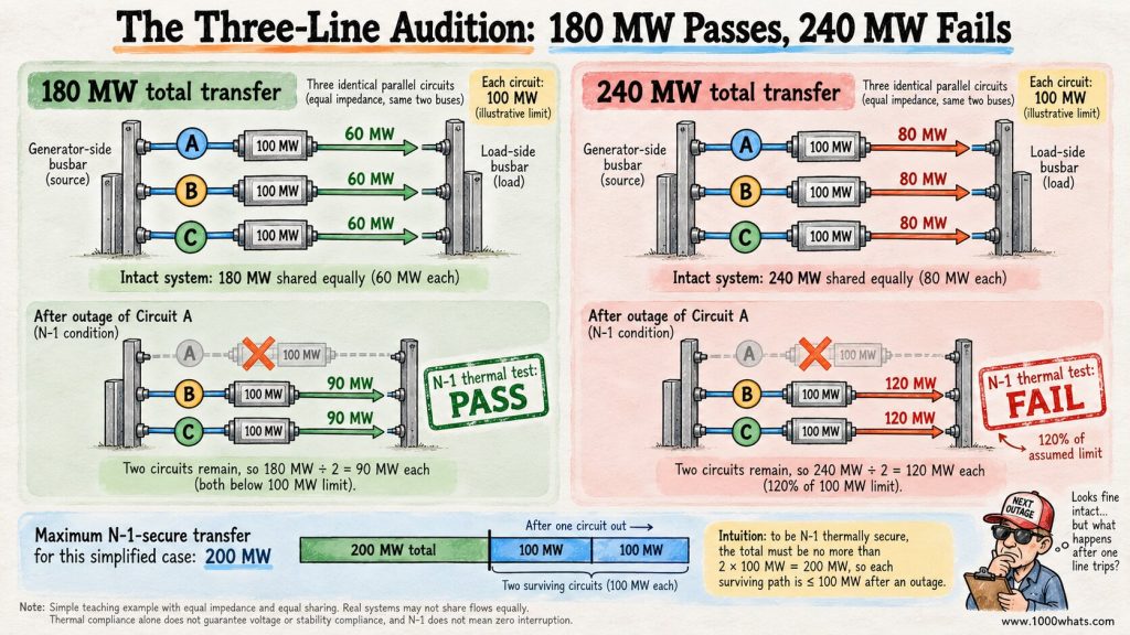
Imagine a generating area connected to a consuming area by three identical parallel transmission circuits. Each circuit has an illustrative transfer limit of 100 MW. They connect the same two buses, have equal electrical impedance, and we ignore losses, reactive power, and all other constraints for this teaching example.
With all three in service, an export of 180 MW divides equally:
180 MW ÷ 3 = 60 MW per circuit.
Each line is comfortably below its 100 MW illustrative limit. The grid looks relaxed. The operator might even finish a sandwich.
Now the planner removes Circuit A.
The 180 MW still needs to reach the consuming area. Under our simplified equal-parallel-path assumptions, it divides between the two surviving circuits:
180 MW ÷ 2 = 90 MW per surviving circuit.
Both are below 100 MW. This example passes the thermal part of its N-1 test.
Now turn the original transfer up to 240 MW. With all three circuits in service, each carries only 80 MW. Nothing is overloaded. Everybody looks innocent.
Remove one circuit, however, and the remaining two must each carry:
240 MW ÷ 2 = 120 MW.
That’s 120% of the assumed limit. The post-contingency case fails this thermal test, even though the intact network was perfectly happy.
| Scenario | All three available | After one circuit fails | Thermal N-1 result |
|---|---|---|---|
| 180 MW transfer | 60 MW per circuit | 90 MW on each survivor | Passes the example |
| 240 MW transfer | 80 MW per circuit | 120 MW on each survivor | Fails the example |
| 200 MW transfer | 66.7 MW per circuit | 100 MW on each survivor | Exactly at the assumed limit |
Under these assumptions, the N-1-secure transfer limit is 200 MW, not the 300 MW suggested by adding three intact-circuit ratings.
The missing 100 MW isn’t a billing error. It’s the capacity the system cannot count on using while still being prepared for one circuit to disappear.
Important reality check: real transmission lines are primarily constrained by current, temperature, voltage, and stability limits, not a universal MW sticker. Their loading is often expressed in amperes or MVA. Our 100 MW limit is a deliberately simplified equivalent real-power limit for this example. Actual post-outage flows also depend on network impedance, topology, voltage, generation, and demand.
Why electricity refuses to follow the emergency exit signs
At this point, the obvious idea is to draw a map, mark the broken line in red, and tell the electricity to use the other route.
Unfortunately, electricity has never attended a traffic-management seminar.
In an interconnected AC network, power flows are determined by the electrical properties of the network, including impedances and voltage angles. Operators influence those flows through generation dispatch, network configuration, transformers, and other equipment. They do not generally assign each megawatt a preferred highway.
That means the outage of a line in one part of the network can increase loading on a different line that looks geographically unrelated. The electrical consequences follow the network, not the story we tell ourselves about where power “ought” to go.
This is the crucial distinction between grid congestion and a literal traffic jam. Cars can choose an exit. AC power flows obey circuit laws, which are famously unmoved by polite suggestions.
Engineers sometimes use a line outage distribution factor, or LODF, as a screening tool. In a suitable linearized power-flow model, it estimates how much the flow on one surviving line changes when another line is removed.
For example, if a line was carrying 70 MW and the estimated change after another line trips is +25 MW, its predicted post-outage flow is 95 MW. That may be acceptable against an illustrative 100 MW limit. A +40 MW change would produce 110 MW and call for a closer look or corrective action.
LODFs are approximations based on model assumptions, not a substitute for detailed AC power-flow and stability studies. But they reveal a lovely truth: sometimes the most important thing about a transmission line is what happens to other lines when it stops working.
The contingency list: who is allowed to miss opening night?
Not every screw, cable tie, and coffee machine in the transmission operator’s headquarters gets its own simulation. Engineers establish a contingency list defining the events that must be assessed.
Depending on the system and rules, it may include the loss of a transmission circuit, a transformer, a generating unit, a significant reactive-power device, or another relevant element. A contingency may also involve several components disconnected as the consequence of one initiating event, such as protection actions following a fault.
That last detail matters. “Single contingency” is not always identical to “exactly one physical object disappears.” If one credible event takes out multiple elements, the study must represent the event as defined by the applicable rules.
And no, you cannot rescue a bad result by quietly removing the inconvenient outage from the list. The grid is not an exam where you get to erase the difficult questions.
European rules distinguish ordinary and exceptional contingencies and allow specified exceptions and coordinated approaches. North American planning standards likewise distinguish event categories with different performance requirements. There is no single universal N-1 checklist that fits every network and every asset.
Surviving means more than keeping the wires warm
Our three-line example checked one thing: thermal loading. A real grid operator has more concerns than a line getting a little too enthusiastic about carrying current.
| What engineers check | What could go wrong after the outage? | Why it matters |
|---|---|---|
| Thermal loading | A surviving line or transformer exceeds its applicable rating | Overheating and equipment damage risk |
| Voltage | Bus voltage falls or rises outside permitted limits | Equipment and system operation can become unsafe or unstable |
| Transient and dynamic stability | Machines or controls fail to remain in a stable operating condition | A local disturbance can grow into a larger problem |
| Frequency and reserves | A major generating unit trips, creating a supply-demand imbalance | Frequency must be arrested and restored |
| Protection and fault clearing | Faults or protection actions disconnect more equipment than expected | The actual event may be larger than the first simplified diagram |
Some limits are continuous. Others are emergency ratings valid only for a defined duration. A circuit may safely carry a higher current briefly while an operator redispatches generation, but it cannot simply live there forever because the control room finds the number aesthetically pleasing.
That is why a study must specify which limit applies and for how long. An overload that can be relieved within the permitted emergency-rating window is not the same as an uncontrolled overload with no workable remedy.
And a thermal pass does not guarantee a voltage or stability pass. Electricity systems have several ways to fail an audition.
How to rehearse a catastrophe without upsetting the customers
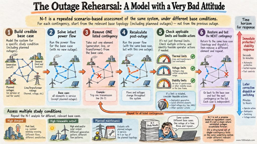
A practical contingency-analysis workflow looks like this:
- Build a credible base case. Represent the network topology, generation, demand, planned outages, interchange, equipment ratings, and relevant controls.
- Solve the intact system. Calculate flows, voltages, and other quantities before anything goes wrong.
- Remove one listed contingency. A circuit, transformer, generator, or another defined event leaves the model.
- Recalculate and assess. Examine post-contingency flows, voltages, stability, and any other applicable security limits.
- Test the remedies. If the case fails, determine whether feasible preventive or corrective actions can bring it within the applicable requirements.
- Restore the model and repeat. Next contingency, please. The simulated disaster department never runs out of appointments.
One sunny Sunday at minimum demand is not enough. Planners study relevant combinations of high and low demand, generation patterns, seasons, equipment availability, and other credible conditions. Operators also use forecast and near-real-time information to assess the system they actually have, not the one depicted on a brochure from three years ago.
In a large network, the list of cases can be substantial. Computers do the arithmetic. Engineers decide whether the assumptions are credible, whether the proposed remedy can actually happen in time, and whether a result that looks fine on a screen is physically meaningful.
A model that says “just move 400 MW to the other side of the country in two seconds” may be mathematically enthusiastic and operationally unemployed.
One line fails. What happens in the first seconds?
The dress rehearsal needs to respect the clock. Not everything happens at the same speed.
A fault may be detected and cleared by protection systems extremely quickly. The electrical network then responds to the new topology. Power flows change; voltages may shift; a generator loss can create a frequency imbalance. Automatic controls and reserves begin responding on their relevant timescales.
Later, operators may redispatch generators, adjust transformers, change network configuration, activate contracted flexibility, or take other coordinated actions.
But a plan that depends on a telephone call and a 15-minute redispatch cannot prevent a stability problem that unfolds in the first second. Conversely, an emergency line rating may allow a brief overload if an effective action can be completed before the permitted duration expires.
There are two different questions here: Can the system survive the immediate event? And can it settle into a secure operating condition afterward?
Both matter. The second is no consolation if the first goes badly.
The healthy line that was told to do less work
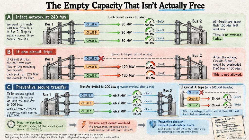
Return to our three circuits. All are intact. At 240 MW total transfer, each carries 80 MW against the illustrative 100 MW limit.
An ordinary observer sees 20 MW of unused capacity on each line and asks why the operator is being difficult.
The operator sees a future in which one line trips and the remaining two jump to 120 MW each.
So the operator may limit the transfer to 200 MW, or use another feasible remedy that changes the relevant post-contingency flows. This is security-constrained operation: a decision made today because of what could happen next.
The network can therefore be constrained even when no equipment is currently overloaded.
That’s one reason grid congestion can feel so mysterious. The visible line isn’t full. The hidden constraint is the line’s future workload after somebody else fails.
It’s the electrical equivalent of a theater manager refusing to sell every seat because one exit must remain available. The seats are empty. The fire code remains unimpressed.
And the backup plan has a price tag
Suppose the cheapest generator could supply another 30 MW across a constrained corridor, but doing so would violate a post-contingency limit.
Instead, the system operator arranges for 30 MW less generation on one side and 30 MW more on the other, assuming the locations and operating conditions make this an effective redispatch.
Imagine the generator reducing output has a marginal cost of €40/MWh and the generator increasing output costs €90/MWh. Ignore startup costs, ramping limits, compensation details, and losses for this illustrative calculation.
The incremental operating cost is:
30 MW × (€90/MWh − €40/MWh) = €1,500 per hour.
Over four hours, that’s €6,000 in additional modeled generation cost.
Nothing broke. No consumer lost power. The system paid to be ready for a failure that never occurred.
Which sounds wasteful until you consider the alternative: paying nothing for security and discovering that a single fault can turn into an uncontrolled outage.
That trade-off is one reason transmission expansion, flexibility, congestion management, and energy-market design are inseparable. My electricity balancing explainer covers another part of the operator’s job: keeping supply and demand matched as conditions change.
Be careful with the economics, though. The €1,500/h figure is an illustrative dispatch-cost difference, not a universal redispatch payment or electricity market price. Real settlement arrangements differ, and the physical effectiveness of redispatch depends on where resources sit in the network.
Preventive action versus corrective action: two kinds of stage manager
There are broadly two ways to keep the rehearsal from becoming a real disaster.
Preventive measures are taken before a contingency occurs. They may reduce transfer, change dispatch, or adjust network conditions so the system is prepared for the specified outage.
Corrective measures are activated after the event, provided the network can remain safe while the response takes effect.
| Possible action | What it changes | Important limitation |
|---|---|---|
| Generator redispatch | Changes where power is injected into the grid | Requires available units, ramping capability, and effective locations |
| Network switching or transformer adjustment | Changes topology or the distribution of flows | May create new constraints elsewhere; switching must be safe |
| Storage or demand response | Changes injection or consumption at useful locations and times | Limited by duration, availability, controls, and contracts |
| Additional transmission capacity | Increases structural ability to withstand outages | Capital-intensive and often slow to permit and build |
| Automatic remedial-action scheme | Responds rapidly to a specified event | Needs reliable detection, coordination, and approved design |
The correct remedy is not necessarily “build another line.” Sometimes a relatively small change in dispatch helps. Sometimes a transformer setting matters. Sometimes the answer really is an expensive new corridor with a very long planning application.
Engineering is the art of finding the least painful option that still obeys physics. Accounting gets invited to the meeting shortly afterward.
When a generator calls in sick, frequency answers the phone
So far we’ve mostly removed transmission lines. But a large generating unit can disappear too.
Imagine a 600 MW generator trips while operating at full output. Unless some other resource responds, generation is suddenly 600 MW below demand. Frequency begins to fall in the affected synchronous system.
The response involves system inertia and fast frequency controls, followed by reserves and other balancing actions. I explain those mechanisms separately in grid inertia and ancillary services.
Here, the relevant security question is whether the system has an adequate and sufficiently fast response to the credible loss, under its applicable rules and operating conditions.
Notice that the answer is not necessarily “keep a second 600 MW generator running idle beside the first.” A large interconnected system can combine responses from many resources. The adequacy, speed, location, and technical requirements of those responses are what matter.
This also helps separate operational security from resource adequacy. Having enough resources to serve demand over a season is not the same as being able to withstand a sudden fault this afternoon. A system can be well supplied with annual energy and still be vulnerable to a particular contingency.
Maintenance: when the understudy also needs a day off
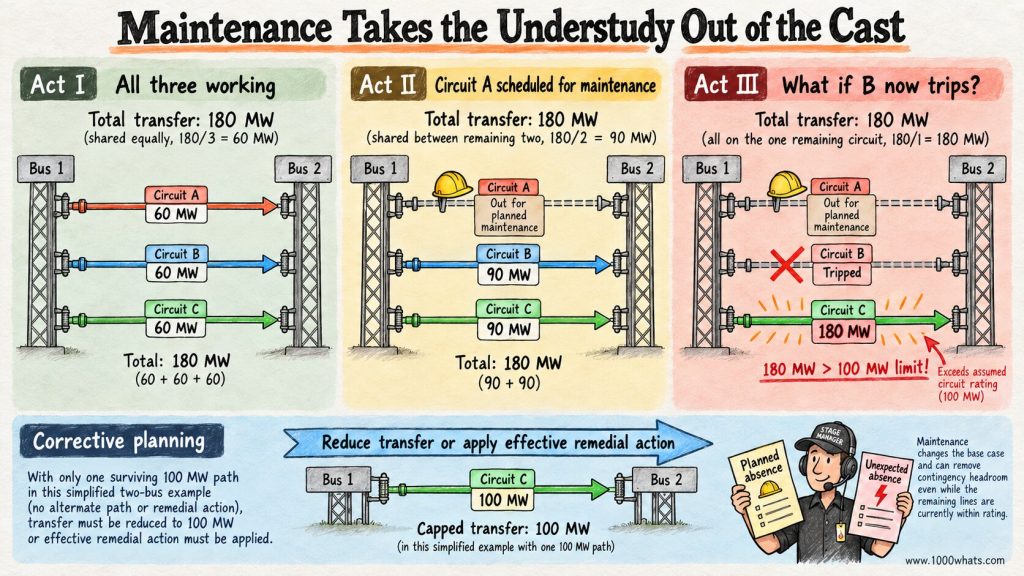
Remember our three 100 MW circuits carrying a combined 180 MW? All three in service: 60 MW each. One failure: 90 MW on each survivor. Fine.
Now schedule Circuit A for maintenance. The other two carry 90 MW each.
At first glance, the network still looks safe. Both lines are below 100 MW.
But what if Circuit B now trips?
The entire 180 MW would, in our simplified example, fall on Circuit C. That’s 180 MW against a 100 MW limit.
The grid has not become more accident-prone because the maintenance crew arrived. It has simply lost a layer of redundancy. If the applicable security requirement must still be met during the planned outage, the operator needs to reduce the transfer to no more than 100 MW or find an effective alternative measure.
This is why outage coordination can resemble a scheduling committee run by people who have seen the future and disliked it. Two perfectly reasonable maintenance requests can become mutually unreasonable when they remove the same system’s remaining options.
In European operational planning, the base topology explicitly includes planned outages. The N-1 analysis then examines relevant additional contingencies from that starting situation.
N-1, N-1-1, N-2: the sequel nobody asked for
Once you’ve mastered the single-failure rehearsal, engineers introduce sequels.
N-2 generally refers to assessing the loss of two relevant elements under the specified event definition. N-1-1 is often used for a sequence in which one contingency occurs, system adjustments may be made, and then a second contingency occurs. The exact terminology and requirements vary by planning standard.
Those are not interchangeable. Two components disappearing simultaneously can produce a different outcome from one failing, the operator adjusting the system, and another failing later.
And a common-mode event complicates matters further. Two circuits may share a tower, right-of-way, or other vulnerability. A single physical event might disable both. Calling them two independent circuits on a diagram does not give them independent weather.
That is why planners study credible multiple-element events and exceptional contingencies where applicable. North America’s TPL standard distinguishes several planning event categories, including sequences of overlapping single contingencies. The labels are not simply a global ranking of how much pessimism the planner has consumed with breakfast.
Why N-1 cannot promise that your lights will never flicker
Let’s be explicit about the limits of the promise.
N-1 does not guarantee that no customer anywhere will experience an interruption. A faulted local feeder may disconnect its customers before switching or restoration. Distribution networks do not universally have the same redundancy obligations as major transmission systems.
It also does not guarantee survival of every possible storm, cyber incident, wildfire, flood, equipment defect, or simultaneous failure. Some events can remove multiple assets. Some outages propagate in ways a simplified model does not capture. Protection systems and communications can themselves malfunction.
And standards may permit specified exceptions, remedial actions, or defined consequences in certain event categories. It is inaccurate to translate N-1 into “one thing can fail and absolutely nobody will notice.”
The more defensible statement is: the system is planned or operated to withstand its defined contingencies within the applicable security framework.
That’s still a formidable achievement. It just isn’t a supernatural warranty.
The uncomfortable question: what if some failures are much likelier than others?
Classic N-1 analysis is largely deterministic. Take a defined contingency, model it, check whether the result is acceptable. Then repeat.
But real failures don’t arrive with equal probability or equal consequences.
A heavily exposed overhead line during a severe storm may face different risks from an underground cable on a calm day. Two nearby circuits may be affected by the same wildfire. The consequence of losing a line serving a remote area may differ from the consequence of losing a major cross-border corridor.
This is where probabilistic risk assessment can complement N-1 analysis. Rather than considering only whether a scenario passes a specified threshold, risk-based approaches also consider how likely events are and how severe their consequences may be.
ENTSO-E describes probabilistic assessment as complementary to the N-1 criterion, not a magic replacement for it.
The distinction is subtle but important. A system might pass all the single-contingency cases on its list and still face meaningful risk from correlated events. Conversely, not every imaginable two-component failure deserves the same investment response. Risk is about both the possibility and the consequence.
The professional pessimist has now hired a statistician. Their conversations are not cheerful, but they’re useful.
Does the energy transition change the rule?
It changes the operating conditions and the available responses, sometimes dramatically.
More wind and solar can shift power injections geographically and hourly. Large power flows may emerge in corridors that once had modest traffic. A hot day can increase demand while changing the thermal conditions under which overhead lines operate. Batteries can provide fast support, but their duration, state of charge, and location matter.
Inverter-based resources also bring different control and fault-response characteristics from conventional synchronous machines. Their behavior must be represented appropriately in relevant studies.
None of this makes N-1 obsolete. It makes accurate contingency modeling and workable remedial actions more important.
The system that passed a study with yesterday’s generation mix may need a fresh study when the geography of generation changes. A wind farm in a remote area does not merely add megawatts to a national total. It changes which lines carry power, when, and under which outage conditions.
And the fact that a line is not overloaded in the intact network does not settle the question of whether additional generation can be accommodated securely. Sometimes the missing piece is not more generation. It’s a better answer to “What happens if this circuit trips?”
Does N-1 mean building two of everything?
No. Thankfully. The planet has enough expensive construction projects without every transformer demanding an identical twin and a matching birthday cake.
Reliability can come from meshed networks, spare transfer capability, alternative supply paths, flexible generation, automatic controls, operating reserves, storage, demand response, and other coordinated measures. Some critical installations do use highly redundant equipment, but N-1 does not translate into a universal 100% hardware duplication rule.
Remember our three-line example: we did not add a fourth line. We simply found that the secure transfer level was lower than the sum of intact ratings. Other designs and controls might allow a different secure transfer level.
Nor is more equipment automatically safer if the assets share a vulnerability. Two lines on the same towers may look redundant until the same event takes out both. Real resilience asks whether the alternatives are genuinely independent enough for the threats being considered.
Five questions worth asking when someone says “the grid is N-1 secure”
The phrase sounds reassuring. It becomes genuinely informative when you ask a few more questions.
- Against which contingency list? Single circuits, transformers, generators, and which exceptional events?
- Under which operating conditions? Peak demand, low demand, high renewable output, maintenance outages, and credible forecasts?
- Against which limits? Thermal ratings, voltage, stability, frequency, and protection behavior?
- With which remedial actions? Are they automatic or manual, preventive or corrective, and fast enough to work?
- For which part of the system? A transmission network, a distribution area, a specific connection, or a particular planning case?
If nobody can answer those questions, “N-1 secure” may be functioning more as a slogan than as an engineering conclusion.
The minus one is simple. Everything around it is where the engineering lives.
Final thoughts
At 3:06 p.m., the engineer removed a transmission line from the model.
At 3:07, another line was carrying too much. At 3:08, the engineer found a dispatch change that could help. By 3:20, the model had survived a different outage and failed a third.
Outside, the real transmission lines continued doing their jobs. Nobody applauded. Nobody knew a tiny simulated catastrophe had just been prevented from becoming an expensive real one.
That is the peculiar beauty of the N-1 criterion. Its success often looks like nothing happening.
No dramatic rescue. No emergency announcement. Just enough margin, enough preparation, and enough good engineering that one bad event stays one bad event.
Electricity networks are complicated machines. We ask them to work every second, through heat, cold, equipment failures, maintenance, and changing patterns of generation. We also ask them not to make those difficulties our problem.
Somewhere in a control room, a professional pessimist is making that possible by breaking tomorrow’s grid today, safely, inside a computer.
It may be the most optimistic job in the industry.
Until next time, stay curious! 😎
Discover more from 1000whats
Subscribe to get the latest posts sent to your email.